In order to ensure that the coordination of the drone flights is as autonomous as possible, it is very essential that the process of recharging of the battery is fully automated. The functions of the Automated Landing and Recharge Systems (ALRS) include:
⦁ Provision of a platform for the landing of the surveillance drones
⦁ Provision of power for the charging of drone batteries through a WIRED connection
⦁ Keeping the battery temperature within acceptable limits during charging
⦁ Protection the drone and the charging contacts from extreme weather conditions
To achieve the goals stated above there are two major parts of the ALRS namely: the Electronic and Electromechanical systems.
The Electronic systems is to be
⦁ Responsible for providing an output voltage for battery charging
⦁ Powered from the mains supply and a backup battery
⦁ Controls the opening and closing of the ALRS motorized cover `
We have the following subunits for the electronic systems which are elucidated upon: rectification unit, Drone battery charger circuit, backup battery charger, Microcontroller Unit
The rectification unit: This unit is meant to provide an unregulated 16V dc output voltage from the mains supply. The output voltage of this unit will be used to charge the backup battery as well as power up the rest of the circuit when mains power is available
Drone battery charger circuit: This unit will produce a 12.4V DC output voltage for charging the LiPo drone battery. During mains failure, the system will be powered from the backup battery source and the battery voltage can range from 12.0 -13.2V. This was carrid out to ensure that none of the components connected to the battery is going to be endangered by the level of voltage used in charging (since the charging will be done with the battery fully loaded in the drones)
Battery charger: This unit is responsible for keeping the backup battery fully charged at all times.
The microcontroller unit: This unit is responsible for the overall control of the ALRS platform. It detects when the drone has landed properly on the platform and controls the cooling fan to cool down the drone battery before commencing the charging process. The microcontroller is also responsible for opening and closing the transparent window covering of the ALRS platform through the motor drive unit. The microcontroller uses two limit switches to determine the limits of movement of the motorized protective window
Then the Electromechanical system is to:
⦁ Provide a solid platform for drone landing
⦁ Have a cover that protects the drone and charging contacts from the weather
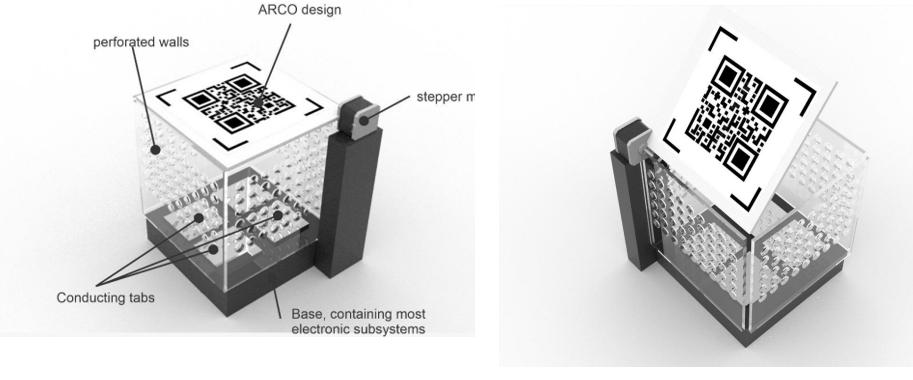
The way to achieve this to have a lid covered with a QR marker for the computer vision system on the drone to be able to land appropriately. The lid will flip open when the drone gets closer for the drone to enter and make contact with the electronic system for the charging to commence. This is made possible by a linear actuator connected from the body of the chassis to the lid that carries out a translational motion and opens the cover in the processes. A sample prototype and the implementation is shown in the figure

Figure 1: The ALRS electromechanical design that shows (a) the components and (b) how It looks when it opens up for the drone landing
Figure 2: The frame for the ALRS showing the linear actuator
For the body of the ALRS chassis decision includes the use of
⦁ Colored Perspex material is being proposed for the construction of the structure for protection against adverse weather conditions.
⦁ The top cover has a ArCo code embossed on it for drone landing purposes.